Detailed specifications of KEL Alternators
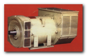
KEL -The Brushless Alternators
ALTERNATOR RANGE: 15- 3000 KVA
|
NFC 51 III - France
VDE 0530 -Germany
BS 500 UK
IEC 2-3 Italy
NEMA - USA
CSA Canada
IS:4722 - India
|
Alternators for marine can be supplied meeting the classification rules of :
Veritas, Det Norske Veritas,Lloyds,American Bureau of Shipping,Rina,Germanischer Lloyd etc.
The KEL's R&D Test center is well equipped to carry out Alternator development, performance optimisation of alternators and validation of product reliability. Modern computerised test facilities are used to monitor to the requisite parameters. Besides the dedication and commitment of its work force has reflected favourably in the quality and standard of the products that roll out from KEL's manufacturing facilities.
Special Alternators are manufactured as per Specifications of customers and KEL has a team of Designers who take up day to day challenges for designing special case alternators.
The latest one being suppplied to Triveni for suppling power to Load balancing machine having 600 V and Thyristor based loads.
Apart from being the choice of leading domestic alternator manufacturers, KEL is rapidly gaining acceptance in the international arena as well.
KEL alternators are being wide range of applications primarily Genset and Steam,Hydro,Gas Turbines, Notably we have supplied Alternator for Steam Turbines in and around Asia for Sugar Mills.
We do provide RTD's & BTD's and Epoxy coating for Gesnsets have Turbine as Prime Mover where conditions are very humid.
Vertical Alternator till 300 KVA are manufactured for Hydro Turbine Application.
|
|
Mechanical
- Single bearing with SAE disc coupling arrangements, also 2 bearing
- Protection IP 23S
|
Insulation
- Main stator and rotor class F or H
- Exciter stator and rotor class F or H
|
COMPOUND EXCITATION SYSTEM
- This system compromises:
- A 3 phase compounding transformer
- An auxillary winding
- 3 phase rectifier bridge
- A voltage regulator(optional upto 125 kva)
These components are mounted at the rear of the alternator in a substanstial terminal box.
|
FUNCTION OF THE COMPOUND SYSTEM
The alternator exciter is supplied with D.C Current from the diode bridge which receives two sources of A.C> power
- The first supplied by the auxillary winding in the stator being proportional to the voltage of the alternator.
- The second supplied by the secondary winding of the 3 phase compounding transformer and being proportional toi the load current and P.F. The resultant current provides an excitation firld current that varies as a function of the load and P.F. to maintain the output voltage resonably constant (self regulating withought A.V.R)
|
Voltage Regulation
- Alternators upto 125 KVA are supplied withought a regulator, the basic compound excitation system maintaining the voltage to within +- 5% after reaching thermal stability(This is better than most countries main supply.)
Electronic AVR can be provided as optional for regulation within +-2%>
The alternator voltage is adjustable by a rheostat over the range 380 to 415V, 50 Hz and 440 to 480V, 60 Hz.
- Alternators above 125 KVA are supplied with a electronic voltage regulator that maintains the voltage to within +-2%
- Voltage adjustment by rheostat
- Power factor range 0.8 to 1.0
- including cold to hot drift
- Compound "BACK-UP" auto regulation system in case of regulator failure by insertion of a rheostat.
Note Alternators can be supplied with windings giving other voltages if so required.
|
ELECTRICAL PERFORMANCE
Apart from the voltage regulation characteristics the compound excitation system gives you the following advantages:
- Voltage build-up from residual magnetism
- Protection against low speed operation
- Good motor starting, the compound system giving 2.5 to 3 times full load capacity.
- Sustained short circuit current of the order of 3 times full load current.
- Volts/hertz responsive - with any abdrupt in speed from the engine a corresponding reduction in voltage output releives the engine load allowing for faster re-establishment of correct speed.
- Voltage dip on application of full load 0.8 P.F. in the order of 15 to 20%.
- Recovery time at constant speed for full load application less than 0.5 seconds.
- Over voltage limited in-case of regulator failure the voltage rise is limited to a value supplied by the compound system(adjustable).
- 3 phase sensed compound system allows good operation with the unbalanced load system.
- Good overload characteristics
|
|
|
Customer
|
Rating(KVA)
|
QTY
|
|
Jindal Polyester & Steel Ltd.
|
1500
|
1
|
|
Shah Murad Sugar Mills, Pakistan*.
|
1500
|
1
|
|
Alpine Industries Ltd. Indore.
|
1250
|
6
|
|
Triveni Engg & Industries Ltd(Turbines) Bangalore.*
|
1250,
600 V
|
1
|
|
BPL Refrigeration LTD Bangalore.
|
1250
|
1
|
|
Composite Steel Mills Ltd. Hyderabad.
|
1000
|
1
|
|
Wipro Fluid Power Bangalore.
|
1000
|
1
|
|
Indian Telephone Industries Bangalore.
|
1000
|
1
|
|
Indian Oil Company LTD (IOCL). Delhi.
|
1000
|
1
|
|
SRI Ram Pistons & Rings Ghaziabad.
|
1000
|
1
|
|
Indian Railways.
|
750
|
All Rajadhanis & Shathabdhis
|
|
* Latest Installations
|
|
|